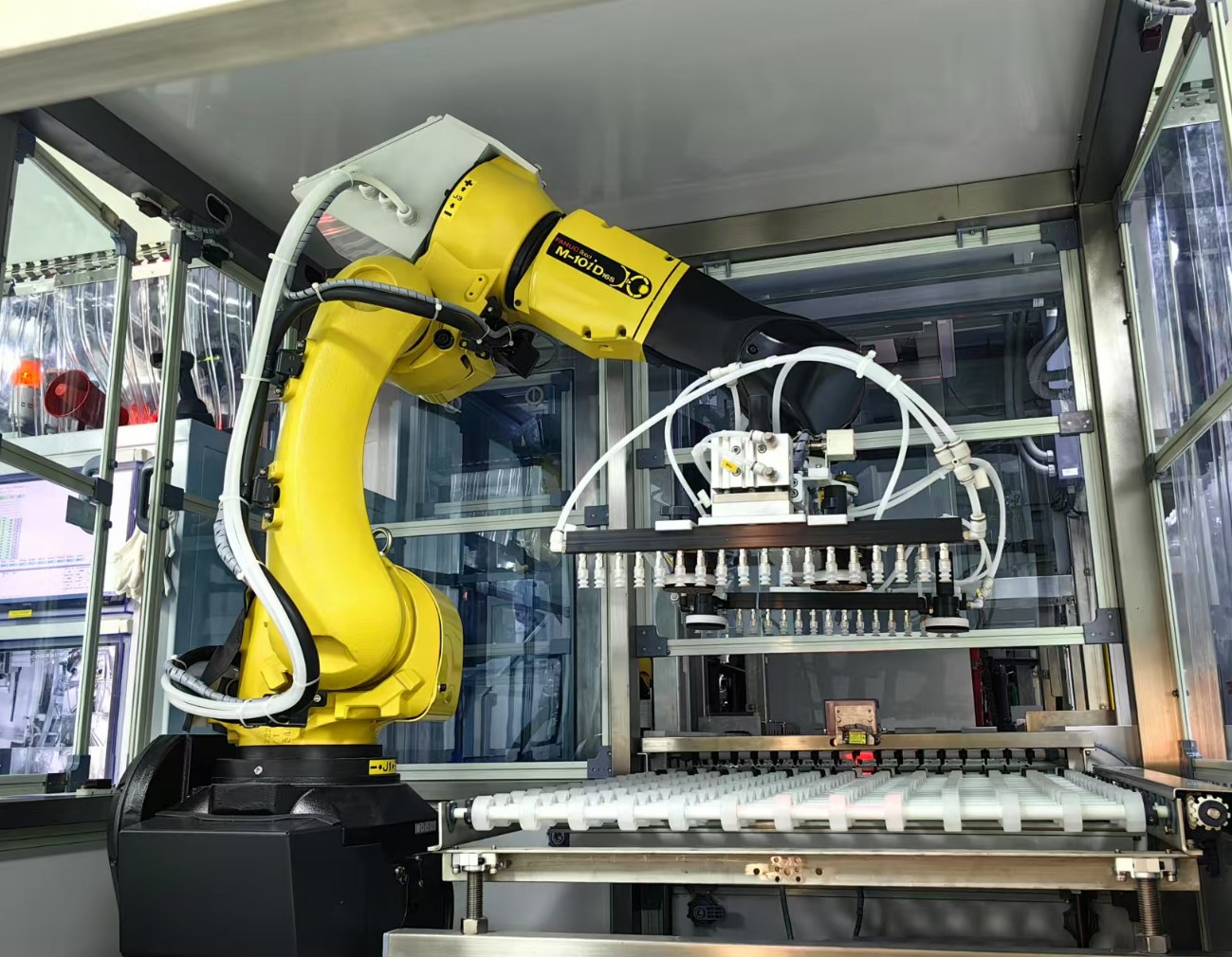
- The solderability of PCB holes affects welding quality Poor solderability of PCB holes will result in solder defects, affecting the parameters of components in the circuit, leading to unstable conduction of multi-layer board components and inner wires, and causing the entire circuit function to fail. The so-called weldability refers to the property of the metal surface being wetted by molten solder, which means that the solder forms a relatively uniform and continuous smooth adhesive film on the metal surface. The main factors affecting the solderability of PCB are: (1) the composition of the solder and the properties of the soldered material. Solder is an important component in the chemical treatment process of welding, consisting of chemical materials containing flux. The commonly used low melting point eutectic metals are Sn-Pb or Sn-Pb-Ag. The impurity content should be controlled in a certain proportion to prevent the oxide generated by impurities from being dissolved by the flux. The function of solder is to help wet the surface of the PCB by transferring heat and removing rust. Generally, white rosin and isopropanol solvents are used. (2) Welding temperature and surface cleanliness of the metal plate can also affect weldability. If the temperature is too high, the diffusion speed of the solder will accelerate. At this time, it has high activity, which will cause rapid oxidation of the PCB and solder melting surface, resulting in welding defects. The surface of the PCB will also be contaminated, which will affect solderability and cause defects, including solder beads, solder balls, open circuits, poor glossiness, etc. 2. Welding defects caused by warping The PCB and components produce warping during the welding process, resulting in defects such as solder joints and short circuits due to stress deformation. Warping is often caused by temperature imbalance between the upper and lower parts of a PCB. For large PCBs, the weight of the board itself may also cause warping. A normal device is about 0.5mm away from a PCB. If the device on the PCB is large, as the PCB cools down and returns to its normal shape, the solder joint will be under stress for a long time. If the device is raised by 0.1mm, it will be sufficient to cause a false solder open circuit. 3. The design of PCB affects welding quality In terms of layout, when the PCB size is too large, although welding is easier to control, the printed lines are longer, the impedance increases, the noise resistance decreases, and the cost increases; Over time, the heat dissipation decreases, making it difficult to control welding and prone to interference between adjacent lines, such as electromagnetic interference from PCB. Therefore, it is necessary to optimize PCB design: (1) shorten the wiring between high-frequency components and reduce EMI interference. (2) Components with large weight (such as exceeding 20g) should be fixed with brackets and then welded. (3) Heating elements should consider heat dissipation issues, and thermal sensitive elements should be kept away from heat sources. (4) The arrangement of components should be as parallel as possible, which is not only aesthetically pleasing but also easy to weld, making it suitable for mass production. The optimal rectangular design for the PCB is 4:3. Do not make sudden changes in wire width to avoid discontinuity in wiring. When the PCB is heated for a long time, copper foil is prone to expansion and detachment, therefore, the use of large areas of copper foil should be avoided.